How to construct a Reuleaux Diagram
Whilst the exact movements of a locomotive’s valves are indeterminate because of the angularity effects of both connecting rods and eccentric rods, a close approximation of its valve events can be found through constructing a Reuleaux diagram in which the angularities are ignored. Porta used these as a first approximation for determining valve events (see his A1 Proposal).
The following sequence of illustrations show how to construct one of these diagrams – in this case using parameters taken from the 5AT:
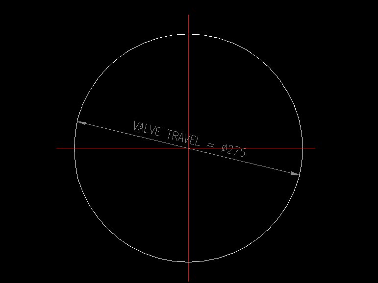
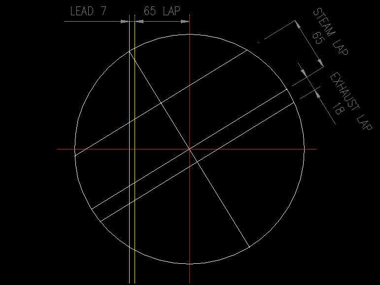
1) Draw a circle with the diameter equal to the valve travel under consideration. In this illustration we draw the diagram for the 5AT at maximum forward cut-off when the valve travel is 275mm (FDC 5 line 39):
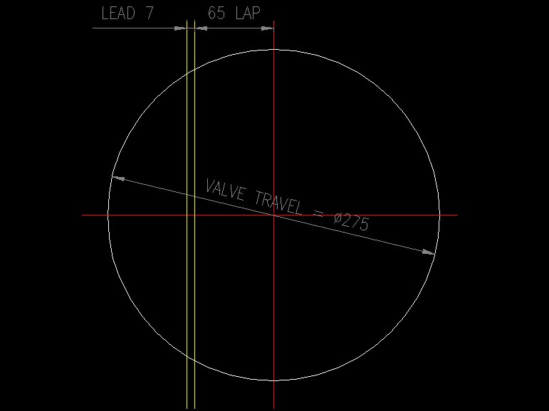
2) Now draw two lines parallel to the vertical axis, one offset by the steam lap, and the other by the lead – in this case 65mm and 7mm respectively:
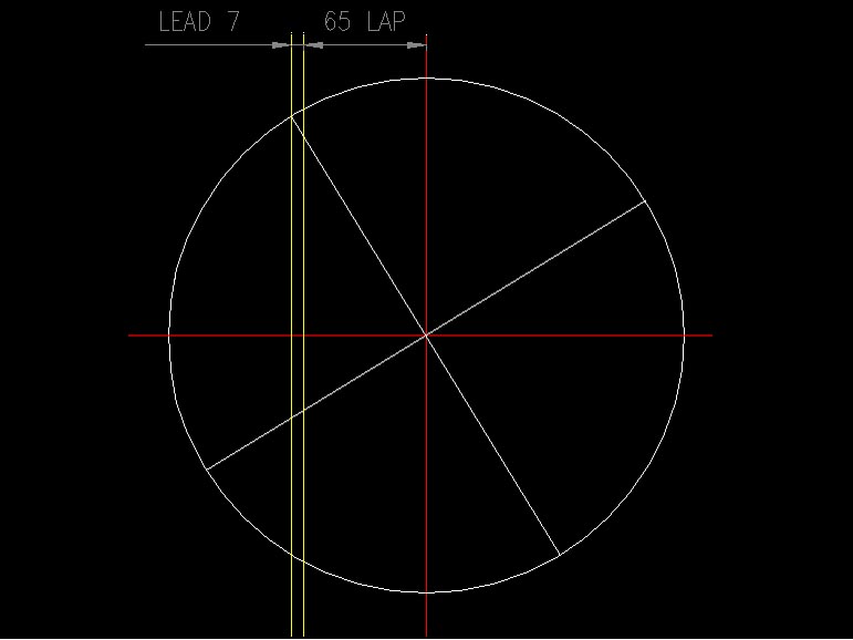
3) Draw a diameter from the point where the Lead line intersects the circle, and another diameter at right-angles to it.
4) Draw two lines parellel to the last-drawn diameter, the first offset on one side by the steam lap (65mm) and the second offset to the other side by the exhaust lap (18mm).
5) It will be discovered that the distance between the upper (steam lap) line and the nearest axis of the circle exactly equals the lead (7mm). Draw Admission, Cut-off, Release and Compression lines as shown below.
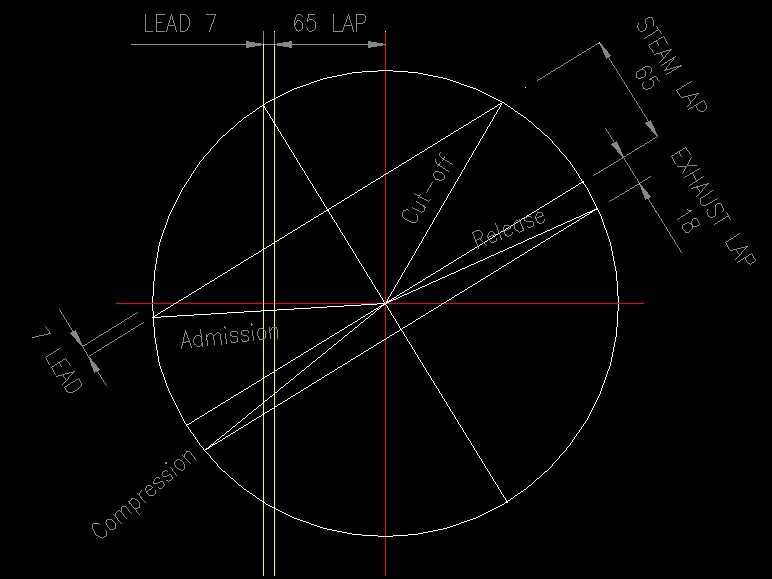
6) Draw verticals from the points where the Admission, Cut-off, Release and Compression lines meet the circle. The distances from the edge of the circle represent the point where each valve event occurs. These distances can be converted to percentages – see below.
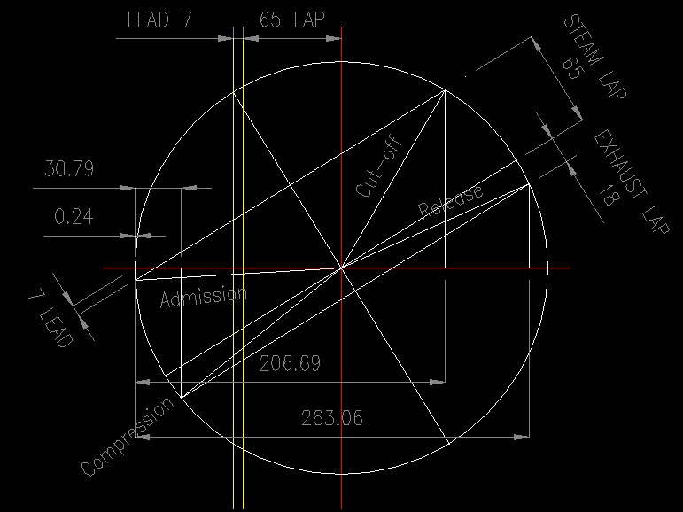
From the diagram above:
- Cut-off occurs at a distance of 206.69mm from the left of circle. 206.69 ÷ 275 = 0.7516 = 75% (i.e. maximum cut-off);
- Release occurs at 263.06 mm or 263.06 ÷ 275 = 0.9566 = 96%
- Compression occurs at 30.79 mm = 30.79 ÷ 275 = 0.1119 = 12%
- Admission occurs at 0.24 mm = 0.24 ÷ 275 = 0.0009 = 0.1%